| Page 0:0 Contents |
Contents |
|
Page 1:0 Contents Page 1:1 Contents Page 1:2 Presentation Page 1:3 Keys Page 1:4 Instruments and controls Page 1:5 Instruments and controls Page 1:6 Instrument panel Page 1:7 Warning lights Page 1:8 Ignition switch/steering wheel lock, parking brake Page 1:9 Headlights, instrument panel light Page 1:10 Direction indicator stalk, fullbeams/dipped beams and headlight flasher Page 1:11 Cruise control Page 1:12 Windscreen wipers, headlamp wipers Page 1:13 Windscreen wipers, headlamp wipers Page 1:14 Heated rear window, electrically heated passenger's seat, hazard warning lights Page 1:15 Electrically operated window winders Page 1:16 Climate system Page 1:17 Climate system Page 1:18 Clock, cigar lighter, ashtrays Page 1:19 Radio, tape player |
| Page 1:0 Contents |
| Personal Information Name................................................... Address................................................ Tel. No. ................................................ Driving Licence No. ............................ Insurance Company ............................ Insurance Policy No. ......................... |
Nearest Volvo Dealer Name............................................ Address......................................... Tel No. ......................................... Garage manager.................................. Tel No. ...................................... |
Car Information Type Designation................................ ChassisNo. ........................... Engine No. ................................. License Plate no. ........................... |
|
When you need service:the autohized workshops maintain and repair your car according to the instructions issued by the Volvo Factory-and always with genuine Volvo spare parts. |
| Page 1:1 Contents |
Presentation 2
| DRIVING |
| Instrumentens switches and controls 4 Instrument panel light, indicator/warning lights, ignition switch/ steering wheel lock, parking brake, direction indicator stalk, windscreen/headlamp wipers, heated rear window, electrically operated window winders, heating and ventilation, climate unit, clock, cigar lighter, ashtrays, radio and tape player. Interior details 20 Courtesy light, rear vieuw mirrors, seats, child safety, seat belts |
Doors, locks, boot lid and bonnet 26 Doors and locks, boot lid bonet, tank filler cap. Sarting and driving 29 Running-in, economic driving, starting the engine, manual gear- box with overdrive, automatic transmission, towing, caravan/ trailer roof rack, points worth noting. |
| SERVICING |
| Volvo-Service, points worth noting, engine compartment 39 Oils, fluids, lubrication and cooling systems 43 Engine, transmission, final drive, brakes, clutch, power-assisted steering, body lubrication, coolant, drive belts. Elektrical system 50 Changing bulbs, changing fuses. Wheels and tyres 55 Genaral advice, spare wheel, changing wheels. |
Body care 60 Replacing windscreen wiper blades, headlamp wipers, washing, polishing, waxing, touching-up damaged paintwork, rustproof- ing, cleaning upholstery, etc. Wintertime and before a long-distance trip 65 Fault-tracing 66 |
| SPECIFICATIONS |
| Page 1:2 Presentation |
| Note that certain differences may arise between the different markets. This manual, therefore, may contain information additional to what concerns your car. Should you require more detailed information concerning adjust- ments or repairs to your car, please refer to our service manuals which The specifications and constructional data | as well as the illustrations contained in this manual are not binding. We reserve the right to make alterations with- out prior notification. |
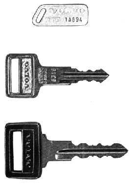
| Page 1:3 Keys |
|
|
Note the number on your keys in your pocket diary or on a slip of paper which you can keep in, e.g., your wallet or handbag. The number for the boot lid/glove compart- ment key is stamped on the key. The ignition/door key has a separate tag with the key number on it. The tag should be separated from the key ring. Should you lose a key, you can order a new one from a Volvo dealer. |
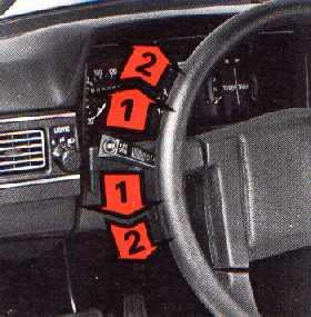
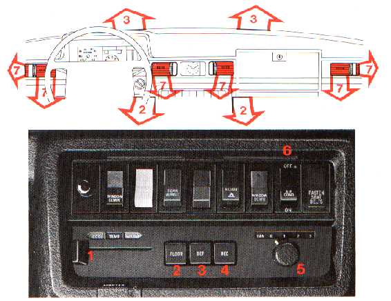
| Page 1:4 Instruments and controls |
| Page 1:5 Instruments and controls |
|
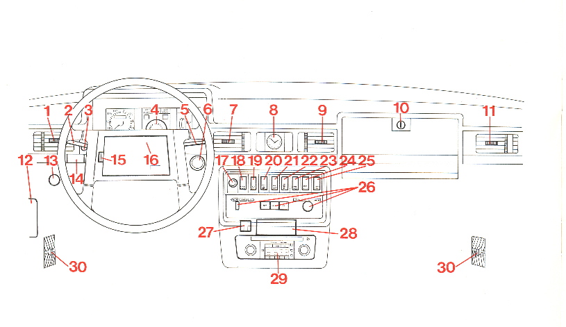
Described on page
 | Described on page Described on page
23 Electrically operated window |
winder, right-hand side 24 Compressor, air conditioning 25 Fasten seat belt light 26 Heater controls 27 Cigar lighter 28 Ashtray 29 Radio, tape player 15 16 24 16 18 18 19
30 Floor vent |
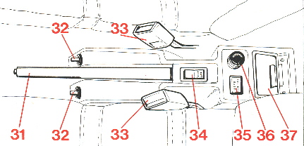
31 Parking brake 32 Outside rear view mirrors 33 Seat belt release 34 Power antenna 35 Fasten seat belt light 36 Cigar lighter 37 Ashtray
17 |
8 21 24 19 24 18 18 Pages 6-20 contain a detailed description of all car's instruments |
and controls. Please note that variations are possible between the various markets due, among other things, to varying legislation. | |
| Page 1:6 Instrument panel |
| A Mileage recorder In kilometres or miles B Speedometer
C Direction indicator: turn left |
D Parking brake light (red) E Headlight main beams (blue)
F Brake circuits failure warning |
G Direction indicator; turn right (green) H Oil-pressure, failure light (red)
I Battery charging failure light |
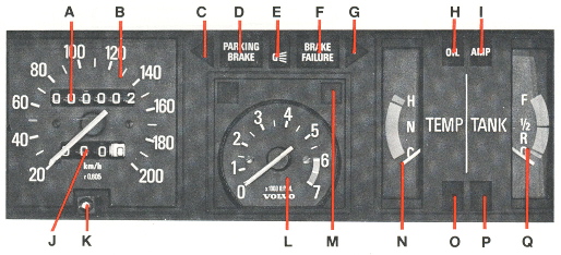
| J Trip meter Figure in right window = 100 metres (or 1/10th mile)
K Trip meter reset knob
L Rev counter |
M Bulb failure warning light (yellow)
N Temperatur gauge
O Overdrive light (green) |
P Choke light (amber) This light stays on while the choke is pulled out.
Q Fuel gauge |
| Page 1:7 Warning lights |
| But they should go on when the ignition is switched on before the engine starts. This tells you wether the lights are functioning or not. All the lights should go out when |
the engine starts (the parking brake light does not, of course, go out until you release the parking brake) |
D Parking brake |
 |
H Oil-pressure faillure light (red) |
M Bulb failure warning light (yellow) |
 |
This goes on when the parking brake between the front seats is applied. |
If this light goes on when driving, then the engine oil pressure is too low. Stop the engine immediately and check the oil level in the engine, see page 43.
It can happen that the lamp goes on after very |
This light goes on if any of the following bulbs are out of order. day running lights (warning light goes on even if main/dipped beams or parking lights are on) dipped beams rear lights brake lights (light goes on each time the brake pedal is depressed). See pages 50-54 for bulb changing. |
F Brake circuit failure warning light (red) |
 |
I Battery charging warning light (red) |
Should the warning light go on even after a defective bulb has been replaced, the corre- sponding bulb on the other side of the car must also be changed. |
If this light goes on when driving and the brake pedal feels rather spongy, then one of the brake circuits is not functioning. However, the car can be driven - but with due care - to a workshop for a check on the brake circuits. |
This light goes on if the alternator does not charge. If it goes on during driving there is either a fault in the electrical system or the fan belts are poorly tensioned and slip. Concern- ing fan belt tensioning, see page 49. Note! If the fan belts run off the pulleys or if the fan-belt tension is so poor that the alter- nator does not charge, not only does the above-mentioned warning light go on but also warning lights D, F and M. This is because of the special legislation on certain markets and is to be regarded as quite normal. |
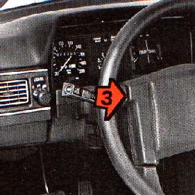
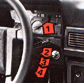
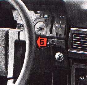
| Page 1:8 Ignition switch/steering wheel lock, parking brake |
Ignition switch/steering wheel lock |
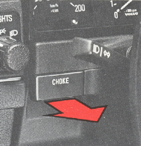 Choke (only on cars with carburettor engine) Pull out the choke fully before starting when the engine is cold. Pulling out the choke a fraction of a inch or so can regulate the engine idling speed to some extent. The choke light on the instrument panel goes on when the choke is pulled out. Use the choke as briefly as possible. |
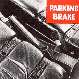 Parking brake (hand brake) The parking brake is situated between the front seats. It operates on the rear wheels. When the parking brake is applied, and the ignition is on, the red PARKING BRAKE light on the instrument panel goes on. We recommended the use of the parking brake several times each week to make sure none of its components jams. | 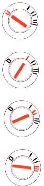 |
O Lock position Steering wheel locks when key is removed. I Intermediate position Certain electrical compo- nents (e.g., heater fan, cigar lighter) can now be operated. II engine-running position The key is in this position when the engine is run- ning. III start position Turn the key to this posi- tion to start the engine. Release the key as soon as the engine starts. It automatically springs back to the "engine- running position". |
A reminder buzzer sounds when the front door is opened and the ignition key is in the switch. It will also sound if the parking lights or head- lights are on when the door is opened. If the car is parked so that there is tension in the steering mechanism, the easiest way to unlock the steering wheel is to turn it a little left and then a little right. | |||
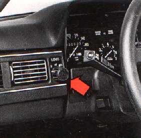
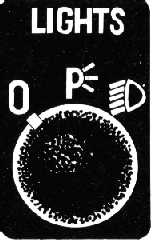
| Page 1:9 Headlights, instrument panel light |
 |
 |
 |
||
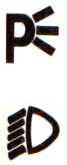
Headlights and parking lights |
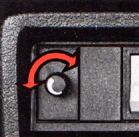
Panel light switch |

|
Ignition switched off: All lights out Ignition switches on: Day running lights (front and rear) on In other words, the day running lights go on automatically when the ignition is switched on. These lights are used when driving in daylight and on well-lit streets and roads when it is dark. In the event the day running lights must not be on during driving, e.g., during a trip abroad, this can be arranged by removing fuse No. 4 (see page 58). (The day running lights are used only on cars marketed in sweden, Denmark and England.) |
|
Parking lights. Day running lights off. The parking lights should only be used for parking, and never when driving. Headlights+parking lights. Day running lights off Naturally, the headlights should be on when driving in darkness on poorly lit streets and roads. A reminder buzzer sounds when the park- ing lights or headlights are on and a front door is opened. The buzzer also sounds if the ignition key is left in the ignition switch and a door is opened |
Clockwise: stronger panel light Anti-clockwise: weaker panel light |
| Page 1:10 Direction indicator stalk, fullbeams/dipped beams and headlight flasher |
 |
 |
Direction indicator stalk, fullbeams/dipped beams and headlight flasher | |
|
1 Lane-changing, overtaking Move the lever a bit up or down, and hold it there, when indicating a change of lane or when overtaking. The stalk will return to the neutral position when released. 2 Normal turns. |
3 Fullbeams/dipped beams (headlights switched on). Move the lever towards the rim of the steer- ing wheel and then release it. 3 Headlight flasher (headlights switched off). Move the lever towards the rim of the steer- ing wheel. Fullbeams remain until you re- lease the lever. |
| If a direction indicator bulb shoud fail, the panel light for that indicator as well as the other indi- cator will blink more rapidly than usual. | |
| Page 1:11 Cruisecontrol |
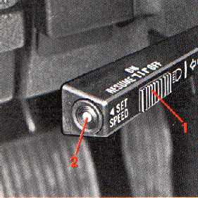
Cruisecontrol (only certain markets) | The switches for operating the cruise control are located on the direction indicator operating stalk. The cruise control is engaged and dis- engaged as follows: 1. Slide switch 1 to ON. 2. Accelerate to the desired cruising speed. NOTE! The cruise control cannot be en- gaged at speeds less than 50 km/h (30 mile/h) 3. Engage the cruise control by depressing switch 2 SET SPEED. Braking automatically disengaged the cruise control. The previously set cruise is re- tained in the computer memory and is resumed by sliding the switch 1 to RESUME. |
Momentary acceleration, e.g., when passing a slow-moving vehicle, does not interrupt cruise control operation. The previously selected is maintained without having to slide switch 1 to RESUME. To select a new cruise speed, repeat steps 2 and 3 above. The cruise control automatically disengages when the ignition is switched off. |
| Page 1:12 Windscreen wipers, headlamp wipers |
 |
 |
|
Windscreen wipers, washers, Headlamp wipers, washers | ||
| 1 Interval sweep position. Move stalk to this position and wipers will make one sweep about every five seconds. rain or fog. 2 Wipe-pause position. Use when you want the wipers to make one or two sweeps only (e.g., when driving in light rain). Hold stalk at this possition with finger, it will return to parking position when released. 3 Windscreen-wipers - normal speed. |
4 Windsreen wipers - high speed. 5 Windscreen washers+headlamp wipers and washers. The windscreen wipers also start with stalk in this position. When the stalk is released, the wipers make 2-3 extra double sweeps. |
NOTE! The headlamp wipers have an overload protection which cuts in when the wiper blades are blocked with, e.g., snow or ice. When this happens, proceed as follows: switch off the ignition and remove whatever is block- ing the blades. Switch on the ignition again. Wait for about 2 minutes before using the wipers. |
| Page 1:13 Windscreen wipers, headlamp wipers |
 |
 |
|
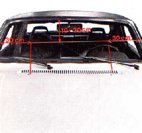
Adjusting the washer nozzles Stick a pin in the nozzles and adjust the posi- tion of the nozzles so that the jets strike the windscreen as shown in the illustration. |
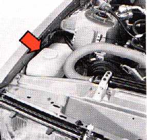
Washer reservoir The washer reservoir serves both the wind- screen and headlamps. It is situated in the engine compartment and holds about 6 litres/ 10.5 UK pints. During the wintertime, the reservoir should be filled with anti-freeze, see page 65. |
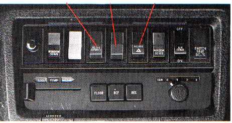
| Page 1:14 Heated rear window, electrically heated passenger's seat, hazard warning lights |
Position of switches |
Rear demist |
Heated passenger's seat |
Hazard warning lights | 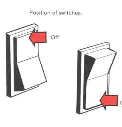 |
|
Heated rear window-rear demistSwitch off once the rear window is free frommist and ice so as not overload the battery unduly. Avoid placing anything near the heating wires that could damage them. Observe due care when wiping the inside of the rear window since rings on the fingers etc., can damage the wires. |
Heated passenger's seatBoth front seats are electrically heated.The heating is controlled by a thermostat and engages automatically below about +25°C (77°F). The passenger's seat heating should be switched off when no one is sitting in the seat. (The driver's seat engages and disengages automatically according to ambient tempera- ture and cannot therefore be switched off.) |
Hazard warning lightsUse the warning lights only when you have tostop or park the car where it might be a possi- ble hazard to other traffic. Note that regulations governing the use of these lights may vary in different places. |
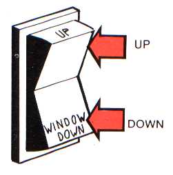
| Page 1:15 Electrically operated window winders |
| Left window |
Rear fog lights |
Right window |
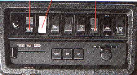 |
 |
Rear fog lightsCars are fitted on certain markets with rear fog lights. These are switched on by depressing the lower part of the switch. Remember that legislation concerning rear fog lights may vary from one country to another. |
Electically operated window | |
|
Both the front doors are fitted with electrically operated window winders. |
The switch springs back to its switched-off position when released. | |
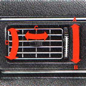
| Page 1:16 Climate system |
Climate system1 TEMPLeft=COOL Right=WARM 2 FLOOR Not pushed in=no air to floor Pushed in=full air to floor 3 DEF (defroster) Not pushed in=weak defrost Pushed in=full defrost 4 REC-(recirculation) This button must be used for cooling. It must be pushed in during the cooling period and if the outside temperature and/or humidity is high. It must not be used for heating. 5 FAN 0=off 3=max The fan must always be on when the air con- ditioning is being used. 6 AIR COND (compressor) Pushing in the button starts the compressor. NOTE! The fan must be engaged in order for the air conditioning to start. 7 Air vents Air flow through these vents reduces if 2 FLOOR and 3 DEF are pushed in. |
 | |
For best heating...1 TEMP --------> WARM 2 FLOOR pushed in 5 FAN ---------> 2 (possibly 3) Close the four air vents on the facia and the two fresh-air vents near the floor. | ||
| Page 1:17 Climate system |
To remove mist...1 TEMP ------> WARM3 DEF pushed in 5 FAN ----->3 7 Facia vents closed. Close also floorvents If snow has fallen, first remove the snow from the air intake in front of the windscreen. At all temperatures above ±0°C, the demois- tening function of the air conditioning system can also be used for rapid removal of heavy misting. Push in 4 REC and 6 AIR COND until the mist has disappeared. ... for coolest1 TEMP --------> COOL4 REC pushed in 5 FAN ------->3 6 AIR COND pushed in 7 Air vents open (5) FAN must be engaged in order to start the compressor for the air conditioning. Note! The car windows and the floor must be closed. Let a Volvo workshop check the air condi- tioning once a year. |
 |
 |
Facia ventsA Closed B Open C Air flow to the side D Air flow vertically |
Floor ventsFloor vents are situated on each side near the floor. Air flow through these vents is regu- lated by the lever in the middle of the vent. Lever forwards-vent opened Lever backwards-vent closed Maximum air flow is obtained with the vents fully open and the air fan off. If the air fan is switched on the fresh air will flow through the air vents on the facia instead. |
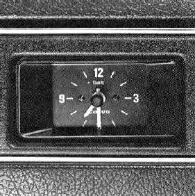
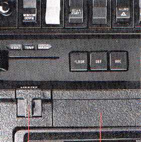
| Page 1:18 Clock, cigar lighter, ashtrays |
 |
 |
 |
| Cigar Lighter Ash trays | Cigar Lighter Ash trays | |
Clock |
Cigar lighter |
Ashtrays |
| The clock is electrically operated from the car battery. To set the clock, push in the knob and turn the hands. |
To use the cigar lighter, push it in fully. It automatically springs back when sufficiently heated. |
To empty the ashtray, draw it out fully, press down its tongue and remove. |
| Page 1:19 Radio, tape player |
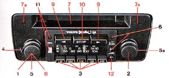
Radio, tape player (optional equipment)Controls, buttons for radio: numbers in blackControls, buttons for tape player: numbers in red Controls, buttons for radio and tape player: numbers in red/black |
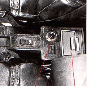
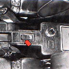
RadioantenneThe power antenna is operated by a switch on the parking brake bracket. THe antenna should be fully up for good radio reception. Note! The antenna should be recessed when the car is about to be cleaned in an automatic washer. Read also the separate instructions for your radio/tape player supplied with this unit. | |
|
1 On/off and volume control 2 Station tuning 3 Wavelength tuning 4 Bass/treble control 5 Balance control, left-right 5a Balance control, front rear 6 ST-MO: Stereo-Mono switch with control lamp |
7 Tape cartridge opening 7a Indicator lamps for tape play 8 Channel selector (tape travel direction) 9 Rapid winding 10 Stop/cartridge eject 11 REC, recording from radio 12 Mic, recording from microphone (acces- (sory, P/N 1128282) | |
![]()