Page 5:1 In case of emergency

In case of emergency

Even if you maintain your car in good running
order there is always the possibility that
something might go wrong such as a puncture,
blown fuse or bulb...

Page 5:1 In case of emergency this index
Page 5:2 Changing wheels
Page 5:5 Replacing bulbs
Page 5:12 Replacing fuses
Page 5:15 Troubleshooting
Page 5:20 Replacing wipers


Page 5:2 Spare tyre
Go To Top of Page.

Changing wheels

Always make a note of the position of the standard wheels before
fitting winter tyres. (i.e. front left etc.)
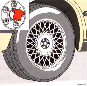
Also, to help prevent wheel imbalance the weheels must be aligned
with the stud on the brake disc. This stud fits into a hole which has
been drilled between two of the wheel's studs.
It also ensures that the wheels after a change - due to puncture or
change from summer to winter tyres - are always in the
same position.

changing wheels
Special spare

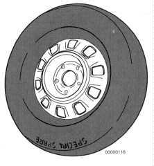
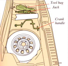
Special spare (certain markets only)

The spare wheel supplied with your car is of the special spare type.
The tyre designation is 155 R15. Your volvo dealer stocks replacement
tyres with this destignation.
The inflation pressure of the tyre is 350 kPa (50 psi) irrespective of
load and where the wheel is mounted on the car.
Note: the special purpose spare wheel may be used only as a tem-
porary replacement for a wheel with a flat tyre and must be re-
placed as soon as possible by a standard tyre.

Remember that this tyre used in combination with standard tyres can
have some effect on the handling of the car. We advise you to observe
a maximum speed of 100 km/h (60 mph) when this spare is inuse
although the tyre is quite suitable for higher speeds.


Page 5:3 Changing wheels

Go To Top of Page.

Spare tyre and jack Ease off hub cap with a screwdriver Slacken wheel nuts


Spare tyre and jack

Sedan
The spare wheel is located beneath the carpet in the boot. The jack
and the tool bag are located in the compartment on the right-hand
side of the boot.

Remember to use the warning triangle if your vehicle causes any type
of obstruction to other traffic. Instructions are on the casing.

Changing a tyre

Removal:
  • Apply the parking brake and engage position P.
  • Place chocks in front of the wheels.
  • Remove the hub cap, use the screwdriver in the tool bag.
  • Unscrew the wheel nuts by 1/2-1 turn, see above.


  • Page 5:4 Changing wheels

    Go To Top of Page.

    Changing wheels
    WARNING!
  • The jack should stand on firm level ground.
  • Never crawl under the car when it is raised.
  • The jack supplied with the car should only be used for changing
        wheels. Axle stands or a garage jack must be used in all other
        cases.
  • Apply the parking brake, select P or R.
  • Place chocks in front of and behind the wheels still on the ground
        Use thick wooden blocks or large stones.
  • The jack should be kept well greased.


  • Place the jack attachment next to the wheel to be raised.
       The jack should "hang" from the attachment. Crank down the foot
       of the jack until it rests on the ground. Make sure that the arm is
       lodged well in the attachment.

  • Jack up the car so that the wheel is off the ground.
  • Remove the wheel nuts and lift off the wheel. Take care not to
       damage the threads on the studs.

  • Fitting

  • Clean the mating surface of the wheel and hub.
  • Fit the wheel, noting the posistion of the small guide stud on the brake
       disc. refit the nuts with the tapered ends facing the wheel.
  • Lower the jack and fully retighten the nuts progressively in diagonal
       sequence. Tightening torque 85 Nm (8.5 kpm).
  • Refit the hub cap.


  • Page 5:5 Replacing bulbs

    Go To Top of Page.

    Headlamp bulbs Parking lights


    Headlamp bulbs

    The 4 headlamps bulbs are accessible from the engine compartment
    To faciltate access to the right headlamp bulb you can remove the
    washer filler tube by lifting it straight up.


    Replacement:
  • Release the spring clip retaining the plastic cover and remove the
       cover
  • Withdraw the connector.
  • Press and turn the spring-loaded retainer anti-clockwise (H4 lamp).
       When replacing the H1 lamp unhook the spring.
  • Lift out the bulb as shown above. (Do not touch the glass).
       There are three guide lugs on the bulb holder. The lugs are asym-
       metrically located to ensure that the bulb is properly fitted.
  • Refit in reverse order to removal.

  • Parking lights

  • Remove the bulbholder.
  • Remove the bulb from the holder by pressing and turning anti-
       clockwise
  • Replace the bulb by pressing inwards and turning clockwise.
  • Press in the bulb holder and check that hte lamps lights.

    Note: Never touch the glass part of the bulb because any contami-
    nation from the fingers will give off fumes when bulb is heated
    thus damaging the reflector.


  • Page 5:6 Replacing bulbs

    Go To Top of Page.

    Replacing bulbs


    Direction indicator bulbs

    The bulbs are accessible from the engine compartment.
  • Switch off the lights and the ignition.
  • Turn the bulb holder anti-clockwise and withdraw the bulb holder
       and the bulb.
  • Remove the bulb from the holder by pressing and turning anti-
       clockwise.
  • Insert a new bulb and fit the bulb holder.


  • Page 5:7 Replacing bulbs

    Go To Top of Page.

    Replacing bulbs


    Tail, light bulbs

    The tail light bulbs are accessible from the boot.
  • Switch off the lights and ignition
  • Slacken the screw securing the protective cover and lower it.
       (The cover is hinged)
  • Turn the bulb holder approx. 1 cm anti-clockwise and withdraw it.
  • Remove the bulb from the holder by pressing in and turning a few
       mm anti-clockwise.
  • Insert a new bulb and fit the bulb holder in the tail light cluster.
  • Check that the bulb lights and refit the cover.


  • Bulbs

    1 Reversing light
    2 Rear foglamp
    3 Brake light
    4 Direction indicator
    5 Direction indicator
    6 Tail light
    7 Tail light
    Rating

    21 W
    21 W
    21 W
    21 W
    21 W
    5 W
    5 W
    Socket

    BA 15s
    BA 15s
    BA 15s
    BA 15s
    BA 15s
    BA 15s
    BA 15s


    Page 5:8 Replacing bulbs

    Go To Top of Page.

    High level brake lights Side direction indicators Numberplate lamps

    High-level brake lights
    (certain markets)

    Remove the cover by pressing the top of the
    cover downwards. Access to the bulb is
    gained by turning the bulb holder anti-
    clockwise. To remove the bulb turn anti-
    clockwise.
    Replace bulb and cover.

    Side direction indicators

    The bulb is removed from the outside.
    To remove the bulb, slide the lens forward
    and withdraw the rear edge. Turn the bulb
    holder 1/4 turn and pull out, but do not dis-
    connect the wiring. Withdraw the blown bulb.


    Numberplate lamps

    Awitch off the lights and ignition. Press the
    bulb housing forward until it is reased from.
    the front edge of the housing.
    Replace the bulb. Ensure that the seal is
    positioned correctly and insert the front edge
    of the lamp housing. Press up the rear edge.


    Bulb

    High-level brake
    lights
    Power


    21 W
    Socket


    BA 15s
    Bulb

    Side direction
    indicators
    Power


    5 W
    Socket


    W 2.1x9.5d
    Bulb

    Numberplate lamps

    Power

    4 W

    Socket

    BA 9s


    Page 5:9 Replacing bulbs

    Go To Top of Page.

    Boot light Engine compartment light

    Boot light

    Depress the catch with a screwdriver and
    remove the lens and bulb housing.


    Engine compartment light

    Insert a srewdriver as illustrated and twist
    off the lens.


    Bulb

    Boot light

    Power

    10 W

    Socket

    SV 8.5

    Bulb

    Engine compart-
    ment light
    Power

    10 W

    Socket

    SV 8.5


    Page 5:10 Replacing bulbs

    Go To Top of Page.

    Vanity mirror Door warning lamps Door step courtesy light

    Vanity mirror

    Insert a screwdriver and turn it to remove the
    lens. Replace the bulb and press the lens back
    into place.


    Door warning lamps

    Both doors have red wartning lamps. to replace
    bulbs insert a srewdriver as shown above and
    twist off the lens. Remove the bulb, install a
    new bulb bulb and replace the lens.

    Door step courtesy light

    There are lights on both sides of the floor.
    To remove the bulb, insert a Phillips screw-
    driver as shown above and twist to remove
    the lens. Install a new bulb and replace the
    lens.


    Bulb

    Vanity mirror


    Power

    3 W


    Socket

    SV 7


    Bulb

    Door warning
    lamps
    Power


    3 W
    Socket


    W 2.1x9.5d
    Bulb

    Door step
    courtesy light
    Power


    5 W
    Socket


    SV 8.5


    Page 5:11 Replacing bulbs
    Go To Top of Page.

    Courtesy light and front reading lights Inside hold Rear reading lights

    Courtesy light and front reading
    lights

    Take hold of the front section of the light as
    shown and pull straight down. Press out glass
    from inside
    Replace the blown bulb and check operation
    before refitting the bulb housing.

    Rear reading lights

    Insert a srewdriver as shown above and
    twist to remove bulb houdsing. Remove and
    replace bulb.


    Bulb

    Courtesy light
    Reading lights

    Power

    10 W
    5 W

    Socket

    S 8.5
    W 2.1x9.5d

    Bulb

    Rear reading lights


    Power

    5 W


    Socket

    W 2.1x9.5d


    Page 5:12 Fuses
    Go To Top of Page.

    Foglamps Fuse replacement


    Foglamps

    Remove the two Phillip screws securing the corner strips and pull out
    the reflector.
    Free the spring clip holding the bulb. Withdraw the connector and fit a
    new bulb. Replace parts in the reverse order. Note: "TOP" on the lens
    Note: Never touch the glass part of the bulb because any
    contaminationfrom the fingers will give off fumes when the bulb is
    heated, thus damaging the reflector.

    Fuse replacement

    If an electrical component fails to function, it is likely that a fuse has
    blown due to an overloaded circuit. the fuses (and relays) are housed
    in the central electrical unit behind the dashboard ashtray.
  • Remove the ashtray. Pull out and depress the tongue.
  • Press up the section marked "electrical fuses-press" and
       remove the ashtray box.
    The fuses do not look conventional ones. they are, however, an
    improvement on and more exact than conventional ones.


  • Page 5:13 Fuses
    Go To Top of Page.

    No Amperage
    1
    2

    3
    4
    5


    6
    7
    8
    9


    10

    11
    12

    13

    14


    15

    16

     
    Main fuel pump
    Central locking, Hazard warning lights, Headlamp
    flasher
    Foglights, Rear foglights
    Brake lights, Electrically operated boot
    Glove compartment light, Clock, Radio, Engine
    compartment light, Electrically operated antenna,
    Door open warning lamp, Vanity mirror,
    Door step courtesy light
    Heated front seats
    Electric Climate Control
    Electrically operated window winders
    fasten seat belt light, Direction indicators,
    Heated front seats, Electrically operated window
    winders
    Heated rear window, Heated door mirrors,
    Electrically operated sun roof
    Tank pump, Heated Lambda-sond (B280F)
    Reversing lights, Cruise control, Disengagement
    of 4th gear - automatic transmission
    Electrically operated cooling fan, Fasten seat belt
    reminder light
    Electrically operated door mirrors, Cigar lighter,
    Radio, Air conditioning, Rear reading light,
    Electrically operated fuel cap cover
    Horn, Windscreen wash/wipe, Headlamp
    was/wipe
    -
    25
    25

    15
    15
    15


    30
    30
    30
    15


    30

    15
    15

    15

    15


    25

    -

    The fuses must be removed to check if any have blown. Simply pull
    them straight out. Refer to the list of fuses for the fuse number. If
    the metal wire is broken, the fuse is defective. Fit a new fuse with
    the same amperage and color as the defective one (see top of fuse).
    Spare fuses are carried at each side of the fusebox; 1 x 15A (blue),
    1 x 25A (light yellow), 1 x 30A (green).


    Fuse replacement


    Page 5:14 Fuses

    Go To Top of Page.

    No Ampére
    17
    18
    19
    20
    21


    22


    23
    24
    25
    26
      R
     

    Left main beam
    Right main beam
    Left dipped beam
    Right dipped beam
    Left parking light, front and rear, Numberplate
    lighting, Illumination of: ashtray, heater control
    panel, heated rear window switch, electrically
    operated sun roof switch. Illumination of instru-
    ments and switches on left of steering wheel.
    Seat belt light, Right parking light, front and rear,
    Illumination of storage compartment between
    front seats, Spot lights
    Radio
    Electrically operated passenger seat
    -
    Electrically operated driver's seat
    Spare fuse (reserve)
    15
    15
    15
    15
    15


    15


    25
    30
    -
    30


    Note: an additional 10A fuse protects ABS circuits. This is mounted
    under the dashboard to the left of the steering wheel.

    Note:The headlamp wipers are protected against overloading by a
    resistor which disengages the wipers if the blades are blockes by snow
    or ice. If this happens, turn off the ignition. Once the obstruction is
    removed, it takes approximately 1 minute the wipers can be used
    again. Check the operation of the headlamp wipers regularly.
    If you find it difficult to remove a fuse, unclip the fuse tool on the
    left-hand side of the fuse compartment and use it as described
    below to remove the fuse.


    Fuse tool


    Page 5:15 Troubleshooting

    Go To Top of Page.


    This section contains information which can be of help in the event of a breakdown. Only those faults
    which can be recified with the vehicle's tool kit are listed.


          THE ENGINE DOES NOT START OR
          IS DIFFICULT TO START

    The instructions for starting the engine have not
    been followd.

    Follow the instructions. See chapter 3.12

    The battery is poorly charged or flat.

    Start the vehicle by using another battery. Refer to chapter 3.13
    Recharge the battery.
    Find out why the battery is poorly charged.

    Poor contact in the electrical system

    Check all leads to spark plugs, coil distributor battery and starter
    motor.

    No fuel reaching engine

    Check that there is fuel in the tank.
    Check that none of the hoses in the fuel system is loose or kinked.
    Check that the fuses for the fuel pump are not faulty (fuses No 1
    and 11). Refer to chapter 5.13

    Blocked air filter/fuel filter

    Change filter.

    Faulty ignition system

    Check spark plugs (electrode gap should be 0.7 mm) and wipe clean.
    Clean distributor cap for cracks and wipe clean on inside.
    Check that all electric leads in the ignition system are clean and
    correctly connected.


    Page 5:16 Troubleshooting
    Go To Top of Page.

          MISFIRING AND ERRATIC ENGINE
          OPERATION

    Faulty ignition system

    Check spark plugs (electrode gap should be 0.7 mm) and wipe clean.
    Clean distributor cap for cracks and wipe clean on inside.
    Check that all electric leads in the ignition system are clean and
    correctly connected.


    Page 5:17 Troubleshooting

    Go To Top of Page.


          ENGINE OVERHEATS
          

    Radiator hose cracked or leaking

    Check and replace if necessary.

    Insufficient coolant

    Check and fill coolant. Refer to chapter 7.8

    Fan belt frayed or belt tension incorrect

    Replace belt or adjust tension.

          TYRE IMBALANCE OR VIBRATION
          DURING DRIVING

    Wheel balance

    Have the wheels re-balanced


          HEAVY STEERING
          

    Incorrect tyre pressure

    Check and adjust tyre pressure.

    Level of oil in power-assisted steering pump
    too low

    Check and fill oil, Refer to chapter 7.5


    Page 5:18 Troubleshooting

    Go To Top of Page.


          SUN ROOF DOES NOT OPEN
          

    Electrical fault

    Check fuse No. 10.

    Fault in sun roof motor

    Remove the screw covers and insert a screwdriver in the holes and un-
    screw the motor cover. Remove the cover. Using a screwdriver, depress
    the plastic pin in the centre of the motor screw and turn the screw to
    close/open the sun roof.


    Sunroof manual


    Page 5:19 Troubleshooting

    Go To Top of Page.


    Seats manual

          FRONT SEATS CANNOT BE MOVED
          

    No power to front seats

    Check that the STOP button is not depressed.
    Check fuse No 24 and 26.

    Fault in motor - front seats

    1 Backrest angle: Insert the crank pin in the small hole in the cover
    plate on the side of the seat. Crank in the direction required.
    2 Backward-forward adjustment: Loosen the clips securing the mat
    (under the rear of the seat). Fold out the mat. Insert the crank as far as
    possible in the adjustment screw socket on the rear support rail. Crank
    in the direction required. The crank is in the tool kit.


    WARNING!

    The Supplemental Restraint System (SRS) is earthed under the
    driver's seat. Do not loosen the two srews earthing the unit. Do
    not earth other electrical components using these screws or any
    other points near them. Faults could occur in the system if it is
    improperly earthed.


    Page 5:20 Replacing wiper blades

    Go To Top of Page.

    Replacing wiper blades

    Replacing wiper blades

    Lift off the wiper arm from the windscreen
    and hold blade at right angels to arm
    Then crimp the ends of the plastic clip at
    the back of the arm.


    Slide the wiper blade along the arm to release
    it from the hook.


    Fit new blade in reverse order to removing
    and make sure that it is properly attached
    to the wiper arm.

    Use a nail brush and lukewarm water
    containing a few drops of washing-up
    liquid to clean wiper blades. If the
    blades still leave marks on the wind-
    screen, fit new ones

    Replacing headlamp wiper
    blades


    Replacing headlamp wiper blades

    Pull out the wiper arm from its pivot point.
    Withdraw the wiper blade. the blade can now
    be clicked into place. The long end points
    towards the radiator grille.


    text en picture's from Owners manual Model year 1990

    Go To Top of Page